


Stunning Radiant answered this
Two general mechanisms are used in producing electricity in solar plant:
1). Solar energy (heat) boils water. The steam drives a turbine, the turbine turns an ordinary generator, which generates electric power.
2). Solar energy illuminates photo-voltaic cells, which produce electric power directly from light.
- 8
Akshat Kaushik answered this
electricity is produced by the solar cells present in the solar pannels of a solar system . A solar cell contains two layers of silicon-boron and silicon-arsenic materials contains losely packed electrons which moves when heat of sun pushes them. And then this electricity is moved by silver wires ( having very low resistance ) and then stored in a battery .
- -1
Harsh Arora answered this
Electrical Machines - Generators
(Description and Applications)
The primary supply of all the world's electrical energy is generated in three phase synchronous generators using machines with power ratings up to 1500 MW or more. Though the variety of electric generators is not as great as the wide variety of electric motors available, they obey similar design rules and most of the operating principles used in the various classes of electric motors are also applicable to electric generators. The vast majority of generators are AC machines (Alternators) with a smaller number of DC generators (Dynamos).
Voltage and Frequency Regulation
Most generator applications require some way controlling the output voltage and in the case of AC machines a method of controlling the frequency. Voltage and frequency regulation is normally accomplished in very large machines carrying very high currents, by controlling the generator excitation and the speed of the prime mover which drives the generator.
- Stand Alone (Island) Systems
- Grid Connected Systems
In smaller, stand alone systems particularly those designed to capture energy from intermittent energy flows such as wind and wave power the voltage and frequency control may be carried out electronically. In principle these control systems are similar to Motor Controls and the the various components are outlined in that section.
In grid connected systems the generator voltage and frequency are locked to the grid system. Changing the energy output from the prime mover does not affect the frequency and voltage but will cause the output current to increase resulting in an equivalent change in the generator output power. When connecting a generator to the grid, it's speed should be run up so that it's output frequency matches the grid frequency before the connection is made.
Generator Power Handling
The mechanical shaft power P in Watts applied to a generator is given by:
P = ωT
Where ω is the speed in radians per second and T is the torque in Newton metres.
As with electric motors, the maximum power handling capability of the generator is determined by its maximum permissable temperature.
Generator Load
Voltage and frequency regulation correct for minor deviations in the generator output as noted above but large changes in the load demand (current) can only be accommodated by adjusting the torque of the prime mover driving the generator since generally, in electric machines, torque is proportional to current or vice versa.
Generator Types
AC Generators (Alternators)
- Stationary Field Synchronous AC Generator
- Generator Speed and Frequency
- Rotating Field Synchronous AC Generator
- Series Wound Generator
- Shunt Wound Generator
- Brushless Excitation
- Cooling
The efficiency of a very large generator can be as high as 98% or 99% but for a 1000 MW generator, an efficiency loss of just 1% means 10 MegaWatts of losses must be dissipated, mostly in the form of heat. To avoid overheating, special cooling precautions must be taken and two forms of cooling are usually employed simultaneously. Cooling water is circulated through copper bars in the stator windings and hydrogen is passed through the generator casing. Hydrogen has the advantages that its density is only about 7% of the density of air resulting in fewer windage losses due to the rotor churning up the air in the machine and its thermal capacity is 10 times that of air giving it superior heat removal capability. - Permanent Magnet AC Generators
- Variable/Switched Reluctance Generators
- Characteristics
- Applications
In a stationary field generator, the stator in the form of fixed permanent magnets (or electromagnets fed by DC) provides the magnetic field and the current is generated in the rotor windings.
When the rotor coil is rotated at constant speed in the field between the stator poles the EMF generated in the coil will be approximately sinusoidal, the actual waveform being dependent on the size and shape of the magnetic poles. The peak voltage occurs when the moving conductor is passing the centre line of the magnetic pole. It diminishes to zero when the conductor is in the space between the poles and it increases to a peak in the opposite direction as the conductor approaches the centre line of the opposite pole of the magnet. The frequency of the waveform is directly proportional to the speed of rotation. The magnitude of the wave is also proportional to the speed until the magnetic circuit saturates when rate of voltage increase, as the speed increases, slows dramatically .
The output frequency is proportional to the number of poles per phase and the rotor speed in the same way as a synchronous motor. See Motor Speed Table.
The alternating current output generated in the rotor can be connected to external circuits via slip rings and does not need a commutator.
Typical applications are portable AC generators with output power up to 5 kilowatts.
Small low cost applications such as domestic wind turbine generators are usually designed to run at high speed. For a given power handling requirement, the higher the speed, the lower the required torque. This means that the generator can be smaller and lighter. Furthermore, the high speed generator needs fewer poles, simplifying the design and reducing the costs.
The power handling capacity of a brushed machine is usually constrained by the current handling capability of the slip rings in an AC machine (or even more by the commutator in a DC machine). Since the generator load current is generally much higher than the field current, it is usually desirable to use the rotor to create the field and to take the power off the generator from the stator to minimise the load on the slip rings.
By interchanging the fixed and moving elements in the above example a rotating field generator is created in which the EMF is instead generated in the stator windings. In this case, in its simplest form, the field is provided by a permanent magnet (or electromagnet) which is rotated within a fixed wire loop or coil in the stator. The moving magnetic field due to the rotating magnet of the rotor will then cause a sinusoidal current to flow in the fixed stator coil as the field moves past the stator conductors. If the rotor field is provided by an electromagnet, it will need direct current excitation fed through slip rings. It does not need a commutator.
If instead of a single coil, three independent stator coils or windings , spaced 120 degrees apart around the periphery of the machine, are used, then the output of these windings will be three phase alternating current.
Classified as a constant speed generator, they have poor voltage regulation and few are in use.
Classified as a constant voltage generator, the output voltage can be controlled by varying the field current. They have reasonably good voltage regulation over the speed range of the machine.
Rotating field machines are used for the high power generating plant in most of the world's national electricity grid systems. The field excitation power needed for these huge machines can be as much as 2.5% of the output power ( 25 KW in a 1.0 MW generator) though this reduces as the efficiency improves with size so that a 500 MW generator needs 2.5 MW (0.5%) of excitation power. If the field voltage is 1000 Volts, the required field current will be 2500 Amps. Providing such excitation through slip rings is an engineering challenge which has been overcome by generating the necessary power within the machine itself by means of a pilot, three phase, stationary field generator on the same shaft. The AC current generated in the pilot generator windings is rectified and fed directly to the rotor windings to supply the excitation for the main machine.
Smaller versions of both of the above machines can use permanent magnets to provide the machine's magnetic field and since no power is used in providing the field this means that the machines are simpler and more efficient . The drawback however is that there is no simple way to control such machines. Permanent magnet synchronous generators (PMSGs) are typically used in low cost "gensets" to provide emergency power.
The voltage and frequency output of the permanent magnet generator are proportional to the speed of rotation and though this may not be a problem for applications powered by fixed speed mechanical drives, many applications such as wind turbines, require a fixed voltage and frequency output but are powered by variable speed prime movers. In these cases, complex feedback control systems or external power conditioning may be required to provide the desired stabilised output.
Generally the output will be rectified and the varying output voltage fed through the DC link to a buck - boost regulator which provides a fixed voltage coupled with aninverter which provides a fixed frequency output.
Similar in construction to the switched reluctance motor, the generator is a doubly salient machine with no magnets or brushes. As the inert, iron rotor poles of the reluctance generator are driven past the stator poles, the changing reluctance of the generator's magnetic circuit is accompanied by a corresponding change in the inductance of the stator poles which in turn causes a current to be induced in the stator windings. A pulsed waveform therefore appears at each stator pole. In polyphase machines the outputs from each phase are fed to a converter which switches each phase sequentially on to the DC Link to provide a DC voltage. The system needs position sensing on the rotor shaft to control the timing of the triggering of the converter switches. These position sensors also enable the current to be controlled by varying the turn on and turn off angles of the output current depending on the rotor position. As with the permanent magnet generator, buck - boost regulators are also used to provide control over the output.
The machine unfortunately is not inherently self exciting and various methods have been adopted to enable start up, including the provision of a DC excitation current from a backup battery through the stator windings during start up, or the use of small permanent magnets embedded in some of the rotor poles.
Compact, robust designs.
Variable speed operation.
The generator phases are completely independent.
Inexpensive to manufacture.
Because they have simple, inert rotors with no windings or embedded magnets they can be driven at very high speed and can operate in high ambient temperature conditions.
Suitable for designs up to megawatt capacity and speeds of more than 50,000 rpm.
Hybrid electric vehicle (HEV) drive systems, automotive starter generators, aircraft auxiliary power generation, wind generators, high speed gas turbine generators.
See also Integrated Starter Generator
- Induction Generators
- Fixed Speed Induction Generator
- Variable Speed - Self Excited Induction Generator(SEIG)
- Operation
- Control
Induction generators are essentially induction motors which are run slightly above the synchronous speed associated with the supply frequency. They have no means of producing or generating voltage unless they are connected to an external source of excitation. The squirrel cage construction is used for small scale power generation because it is simple, robust and inexpensive to manufacture.
Fixed speed induction generators actually run over a small speed range associated with the generator slip. They receive their excitation from the electricity supply grid and can only be run in parallel with that supply. When used on line, they are fine for returning power to the grid from which they derive their excitation current but useless as standby generators when the electric grid goes down. Their limited speed range restricts the possible applications.
Small scale electricity generating systems are quite often stand alone applications, remote from the electricity supply grid, utilising widely fluctuating energy sources such as wind and water power for their source of energy. The fixed speed induction generator is not suitable for such applications. Variable speed induction generators need some form of self excitation as well as power conditioning to be able to make practical use of their unregulated voltage and frequency output.
Self excitation is obtained by connecting capacitors across the stator terminals of the generator. When driven by an external prime mover, a small current will be induced in the stator coils as the flux due to the residual magnetism in the rotor cuts the windings and this current charges the capacitors. As the rotor turns, the flux cutting the stator windings will change to the opposite direction as the orientation of the remanent magnetic field turns with the rotor. The induced current in this case will be in the opposite direction and will tend to discharge the capacitors. At the same time the charge released from the capacitors will tend to reinforce the current increasing the flux in the machine. As the rotor continues to turn the induced EMF and current in the stator windings will continue to rise until steady state is attained, depending on the saturation of the magnetic circuit in the machine. At this operating point the voltage and current will continue to oscillate at a given peak value and frequency determined by the characteristics of the machine, the air gap , the slip, the load and the choice of capacitor sizes. The combination of these factors sets maximum and minimum limits on the speed range over which self excitation occurs. The operating slip is generally small and the variation of the frequency depends on the operating speed range.
If the generator is overloaded the voltage will collapse rapidly providing a measure of built in self-protection.
In variable-speed operation, an induction generator needs a converter to adapt the variable frequency output of the generator to the fixed frequency of the application or the electricity supply grid. During operation the only controllable factor available in a self excited induction generator to influence the output is the mechanical input from the prime mover, so the system is not amenable for effective feedback control. To provide a controllable output voltage and frequency, external AC/DC/AC converters are required. A three-phase diode bridge is used to rectify the generator output current providing a DC link to a three-phase thyristor inverter which converts the power from the DC link to the required voltage and frequency.
DC Generators (Dynamos)
Direct Current (DC) Generator
The stationary field AC generator described above can be modified to deliver a unidirectional current by replacing the slip rings on the rotor shaft with a suitable commutator to reverse the connection to the coil each half cycle as the conductor passes alternate north and south magnetic poles. The current will however be a series of half sinusoidal pulses just like the waveform from a full wave rectifier as shown below.
The output voltage ripple can be minimised by using multipole designs.
The construction of a DC generator is very similar to the construction of a DC motor.
The rotor consists of an electromagnet providing the field excitation. Current to the rotor is derived from the stator or in the case of very large generators, from a separate exciter rotating on the same rotor shaft. The connection to the rotor is through a commutator so that the direction of the current in the stator windings changes direction as the rotor poles pass between alternate north and south stator poles. The rotor current is very low compared with the current in the stator windings and most of the heat is dissipated in the more massive stator structure.
In self excited machines, when starting from rest, the current to start the electromagnets working is derived from the small residual magnetism which exists in the electromagnets and surrounding magnetic circuit.
Automotive Alternators
The automotive generator is a variable speed AC machine delivering a fixed level DC output.
The typical generator is a self excited alternating current machine. By using an alternator rather than a DC generator the use of a commutator and its potential reliability problems can be avoided. However, direct current is required for all the loads in the vehicle including the battery and furthermore, the DC output voltage must be constant regardless of the engine speed or the current load. The charging system must therefore include a rectifier to convert the AC to DC and a regulator to maintain the generated voltage within design limits independent of the engine speed.
The rotor is driven by the engine and provides the field excitation. Its speed is directly related to the engine speed and depends on the ratios of the gearing or pulleys driving it. The output current is taken from the stator.
Automotive alternators are usually three phase machines to enable a compact design and at the same time a reduction in the current in the stator windings by spreading it between three sets of windings. This also gives a reduction in the potential voltage ripple after rectification.

- Construction
- Voltage Regulator
The rotor is a claw pole rotor in which the two ends of the rotor form the north and south poles of an electromagnet. The "claws" extend between each other effectively producing alternate north and south poles as they pass the stator poles. The rotor current energising the electromagnet is fed from the stator windings via three auxiliary diodes which rectify it, before passing it through two slip rings to a single rotor coil.
The moving magnetic field associated with the rotor poles causes a current to flow in the stator windings as the field passes over the stator conductors.
The three phase current produced by the alternator is rectified in a full wave, diode bridge circuit to produce a DC output. The alternator EMF is directly proportional to the alternator (or engine) speed. The alternator is however designed to deliver full voltage, normally 14.2 Volts for a 12 Volt nominal lead acid battery, at idle speed and to maintain the output voltage constant at this level as the engine speed increases.
To prevent the battery from being overcharged the DC output voltage must be kept below the 14.2 Volts maximum charging voltage specified for the battery. This is the function of the regulator which senses the alternator's output voltage and if it is greater than the 14.2 Volts reference voltage, provided by a Zener diode, it interrupts the current to the field (rotor) coil. Without a field current the alternator voltage begins to fall. When the alternator voltage falls below the reference voltage, current will be supplied to the field coil once more maintaining the output voltage at the desired level. The rotor thus receives a pulsed DC current over the engine operating speed range, smoothed somewhat by the rotor winding inductance.
Alternative designs monitor the load current on the alternator and provide a feedback mechanism using pulse width modulation to control the stator current to provide a constant output voltage regardless of the load.
- -1
Harsh Arora answered this
Traction Batteries for EV and HEV Applications
Battery Requirements for Typical Traction Applications
Traction applications have traditionally been jobs for Lead Acid batteries but the limitations of Lead Acid batteries, together with the high cost of alternatives, have in turn limited the range of potential battery powered traction applications. A typical family car would need a battery capacity of about 40 KWh to provide a one way range of 200 miles and a 40 KWh Lead Acid battery weighs 1.5 tons.
The situation is changing however as new battery chemistries and supporting technologies have brought with them new technical and economic benefits making battery power viable for traction applications that were previously uneconomic or impractical. In particular, the use of light weight Nickel Metal Hydride and Lithium batteries instead of the heavy and bulky Lead Acid batteries has made practical electric vehicles and hybrid electric vehicles possible for the first time.
General Requirements
It goes without saying that low cost, long life (more than 1000 cycles), low self discharge rates (less than 5% per month) and low maintenance are basic requirements for all applications. Traction batteries generally operate in very harsh operating environments and must withstand wide temperature ranges ( -30°C to +65°C) as well as shock, vibration and abuse. Low weight however is not always a priority since heavy weight provides stability for material handling equipment such as fork lift trucks and the grip needed by aircraft tugs for pulling heavy loads. Low weight is however essential for high capacity automotive EV and HEV batteries used in passenger vehicles and this rules out Lead Acid for these applications.
Protection circuits are also essential for batteries using non-Lead Acid chemistries.
Purchasing Speciications
Traction batteries are very expensive and like all batteries they deteriorate during their lifetime. Customers expect a minimum level of performance even at the end of the battery's life, so the buyer is likely to specify the expected performance at the end of life (EOL) rather than the beginning of life (BOL). Under normal circumstances for EV applications the EOL capacity is specified as not less than 80% of BOL capacity. For HEV applications change in internal impedance is often used as an indicator of lifetime. In this case the EOL internal impedance may be specified as not more than 200% of BOL internal impedance.
This is shown graphically below.
The following outlines the special performance goals and operating requirements for specific automotive applications in addition to the general requirements above.
12 Volt Automotive SLI (Starting, Lighting and Ignition) Battery Operating Requirements
- One short duration deep discharge (50% Depth of Discharge (DOD) with at least 5C rate) followed by trickle charging.
- Battery is essentially constantly fully charged.
- No prolonged operation with deep discharge.
- Typical capacity 0.4 - 1.2 kWh (33 Ah - 100Ah.)
- Peak power 2.4 -3.6 kW (200 - 300 Amps).
PowerNet 36/42 Volt Battery Operating Requirements
- One deep discharge followed by intermittent high current loads.
- No prolonged operation with deep discharge.
- High energy throughput and high cycle life essential, especially if stop/start launch assist function used.
- Tolerant to repeated high current pulses.are n
- Typical capacity over 1 kWh.
- Peak power 5 to12 kW.
The above two applications are not true traction applications though they may be used in mild hybrids which incorporate a start/stop mode (see below).
EV, HEV and PHV Battery Specifications
The diagram below compares the battery power and capacity requirements for a vehicle of the the same size and weight when configured as an EV, an HEV or a PHEV. Battery designs may be optimised for power or for capacity (energy content) but not both (see Energy/Power Tradeoffs in the section on Cell Construction) and so the type of cells used, not just the size, must be selected to suit the application.

In the case of the EV, the battery is the sole source of power so the battery must be sized to deliver that power on a more or less continuous basis. The EV capacity has to be sufficient to achieve the required range but in addition, since it is not desireable to fully discharge the battery, a margin of about 20% is needed so that the depth of discharge will not exceed 80%. A further margin of about 5% is also required the accept any regenerative braking charge when the battery has just been charged. In othe words the battery should dimensioned to provide the required capacity when the maximum SOC is 95% and the maximum DOD is 80%. The continuous discharge rate for batteries optimised for capacity is typically about 1C although some cells may tolerate pulse currents of up to 3C or more for short periods. An EV battery will usually have one deep discharge per day with some intermediate topping up from regen braking and a typical Lithium EV battery lifetime may be from 500 to 2000 cycles.
The battery for an equivalent series hybrid must also be able to deliver the same power as the EV battery because the vehicles are the essentially the same size and weight and for intermittent periods the battery will be the sole source of power. However, because the energy requirement is shared with an internal combustion engine (ICE) the battery capacity required is much smaller. Parallel hybrids may have different power sharing arrangements and so their power requirements could be accommodated by lower power batteries. HEVs thus have the added burden and complication of carrying around two power sources each of which is big enough to power the vehicle on its own.
The result is severe design constraints on the weight and size of the battery which can be accommodated and HEV batteries are typically less than one tenth the size of EV batteries used in the same size vehicle. The unavoidable consequence is that to get the same power out of a battery one tenth the size, HEV batteries must be capable of delivering continuous currents of 10C or more. Fortunately the power requirement is intermittent (but much longer than short pulsed demands) since it is shared with the ICE. Battery capacity is thus less important than power delivery in an HEV because the range can be extended by use of the engine. HEV batteries are therefore optimised for power.
The downside is that because of its low capacity, an HEV battery is continually being charged and discharged during normal operation and can undergo the equivalent of a hundred charge-discharge cycles per day. With deep discharges the battery would unfortunately be worn out in a few weeks. We know however that battery cycle life is increased exponentially as the the DOD is reduced (See Cycle Life and DOD in the section on Battery Life) so HEV batteries must be run at partial DOD in order to extend the cycle life. This means that the battery capacity must be increased accordingly to allow for lower DODs even though the full capacity is almost never used. In the example above the HEV battery operates between 40% and 80% SOC. Longer life can be achieved by using even larger capacity batteries so that the desired capacity can be delivered between SOC limits between 60% and 75%.
Plug in hybrids need to operate part of the time as an EV in the charge depletion mode and part of the time as an HEV in charge maintenance mode. See more detailed PHEV Requirements below. The PHEV battery requirement must therefore be a compromise between an energy storage and power delivery.
This is a major challenge for cell makers.
More detailed operating requirements are outlined below.
Electric Vehicle (EV) Battery Operating Requirements
Large capacity batteries are required to achieve reasonable range. A typical electric car uses around 150 to 250 Watt-hours per mile depending on the terrain and the driving style.
- The battery must be capable of regular deep discharge (80% DOD) operation
- It is designed to maximise energy content and deliver full power even with deep discharge to ensure long range.
- A range of capacities will be required to satisfy the needs of different sized vehicles and different usage patterns.
- Must accept very high repetitive pulsed charging currents (greater than 5C) if regenerative braking required.
- Without regenerative braking, controlled charging conditions and lower charging rates are possible. (At least 2C desirable).
- Routinely receives a full charge.
- Often also reaches nearly full discharge.
- Fuel-gauging critical near "empty" point.
- Needs a Battery Management System (BMS).
- Needs thermal management.
- Typical voltage > 300 Volts.
- Typical capacity > 20 - 60 kWh.
- Typical discharge current up to C rate continuous and 3 C peak for short durations.
Because these batteries are physically very large and heavy they need custom packaging to fit into the available space in the intended vehicle. Likewise the design layout and weight distribution of the pack must be integrated with the chassis design so as not to upset the vehicle dynamics. These mechanical requirements are particularly important for passenger cars.
Hybrid Electric Vehicle (HEV) Battery Operating Requirements
Capacity is less important with HEVs compared with EVs since the engine also provides capacity therefore the the battery can be much smaller, saving weight. However the battery may still be required to provide the same instantaneous power as the EV battery from time to time. This means that the smaller battery must deliver much higher currents when called upon.
A very wide range of batteries is required to accommodate the range of HEV configurations as well as vehicle performance requirements. Some examples are:
- Series Hybrid - The engine is used only to charge the battery. The electrical system provides a variable speed transmission and the electric motor provides the full driving power. Battery requirements similar to EV batteries but lower capacity needed since the charge is kept topped up by the engine.
- Parallel Hybrid - Both the engine and the electric motor provide power to the wheels. Various configurations possible to satisfy different operating conditions. The share of the load taken by the electric motor can range from zero to 100% depending on the operating conditions and the design goals. The battery capacity may be as low as 2 KWh but it must deliver short duration power boosts requiring very high currents of up to 40C for acceleration and hill climbing.
Some examples of different EV and HEV design goals which affect the battery specification are:
- Efficiency Optimisation - This allows the engine to run at its most efficient constant speed simply to keep the battery charged. The electrical drive eliminates the gearbox and provides the variable power output required. This type of drive was first used on Diesel Electric Locomotives. Improved efficiency reduces the fuel consumption which in turn automatically reduces exhaust emissions.
- Efficiency Boost - This uses the battery simply to capture the energy, which would otherwise be lost, from regenerative braking. The captured energy is used to provide a power boost for acceleration and hill climbing.
- Range Extender - This is basically an EV which uses the engine to top up the battery to prevent excessive depth of discharge.
- Stop/Start Mode - This allows the engine to be switched off to save fuel when the vehicle is temporarily stationary at traffic lights or in traffic jams etc. The vehicle moves off under battery power and the engine is restarted when a predetermined speed is reached.
- Town and Country Mode - This allows the vehicle to be used in EV mode while in town or in heavy traffic where it is most suited, and to be used as a normal internal combustion engined vehicle for high speed or long distance highway driving to avoid the range limitations of the EV.
- Multi-mode - Increased versatility is possible by using combinations of the above modes.
- Capacity and Power - In addition to the above operating modes, different batteries will be required to accommodate a range of performance requirements such as economy, top speed, acceleration, load carrying capacity, range and noxious emissions.
The battery has become an important product differentiator, just like the engine is.
Because of the very wide range of HEV operating requirements there are no standard batteries available to match the resulting range of specifications for battery voltage, capacity and power handling and batteries must be custom designed specifically for the intended application.
Some typical requirements are as follows:
- Designed to maximise power delivered.
- Must deliver high power (up to 40C) in repetitive shallow discharges and accept very high recharging rates.
- Very long cycle life 1000 deep cycles and 400,000 - 1,000,000 shallow cycles.
- Operating point is between 15% and 50% DOD to allow for regenerative braking.
- Never reaches full discharge.
- Rarely reaches full charge.
- Needs thermal management.
- Fuel-gauging and complex BMS necessary to regulate battery energy management as well as for driver instrumentation.
- Needs interfacing with overall vehicle energy management.
- Typical voltage > 144 Volts.
- Typical power > 40 kW (50 bhp).
- Capacity 1 to 10 kWh depending on the application.
- As with EVs above, the size, shape and weight distribution of the battery pack must be tailored to the vehicle.
Plug in Hybrid Electric Vehicle (PHEV) Battery Operating Requirements
Batteries for plug in hybrid vehicles must satisfy conflicting performance requirements.
Traction batteries are usually optimised for high capacity in the case of pure electric vehicles of for high power in the case of hybrid vehicles. The EV battery operates down to a deep depth of discharge (DOD) for long range whereas the HEV operates at a shallow DOD for long life.
The plug in hybrid is designed to be used both as an EV for city driving and as an HEV when the charge is depleted or for highway driving. The dual requirements for an extended all electric range, typically forty miles, as well as maintaining high power availability at low state of charge, (see below), impose very stressful conditions on the battery.

The PHEV battery is thus expected to perform both as an EV and as an HEV.
The all electric range requirement can only be satisfied by using larger capacity batteries which adds considerably to the cost and because the high cost, consumers have high expectations about battery lifetime.
Bicycle Battery Operating Requirements
In China where the bicycle is a workhorse, batteries are typically 36 Volt units.
In Europe and USA where bicycles are more often used for recreation, lighter, 24 Volt batteries are more popular.
- Designed as removable modules for convenient indoor charging and as anti theft precaution.
- Should give 5 Amps for 2 hours (240 to 360 Wh depending on the voltage) to allow one hour travel to work. Higher capacity not feasible with Lead Acid because the weight puts limits on portability.
- Peak current 15 Amps.
- Long lifetime minimum 500 cycles or two years.
Marine Battery Operating Requirements
- Requires deep cycle batteries.
- Wide range of capacities and powers required.
- Low weight.
- Must be tolerant to wide range of charging conditions.
- Special environmental conditions.
Materials Handling Equipment Battery Operating Requirements
Similar to EV applications but normally no weight restrictions.
Practical Traction Batteries
For over a century Lead Acid batteries have been the prime source of energy for traction applications because they are both robust and relatively inexpensive. For fork lift trucks, milk floats and similar applications Nickel Iron batteries, which are almost indestructible and have a lifetime of up to ten years, have also been used successfully. The high weight and bulk of these batteries however has precluded their use in passenger cars.
In the 1970s work started on Sodium Nickel Chloride (Zebra) batteries designed for traction applications since they offer the possibility of very high energy densities which could overcome this problem. Unfortunately these are high temperature batteries which must run at 270°C and this has limited their adoption.
The advent of high power Nickel Metal Hydride (NiMH) cells which have overcome both the weight and the operating temperature problems has encouraged several automotive manufacturers to introduce EVs or HEVs using NiMH batteries. NiMH cells operate at normal ambient temperatures. They have a higher energy and power density than Lead Acid cells but not as good as the Zebra cells.
Recently high power Lithium Ion cells which have an even higher energy density than NiMH cells, on a par with Zebra cells, have become available. They also operate at normal temperatures and are just being introduced into new electric vehicle designs.
These new high energy cells however are more vulnerable to abuse and need the support of electronic Battery Management Systems to provide protection and ensure long cycle life.
Traction Battery Chargers
High capacity batteries also require high power chargers to achieve reasonable charging times and the chargers must be compatible with the cell chemistry and should be able to interface with the cell protection circuitry. Just as the battery is matched to the vehicle, the charger must be custom designed and matched to the battery. More information can be found in the section on Chargers.
- 0
Harsh Arora answered this
Solar Power
(Technology and Economics)
The earth receives more energy from the Sun in just one hour than the world's population uses in a whole year.
The total solar energy flux intercepted by the earth on any particular day is 4.2 X 10¹⁸ Watthours or 1.5 X 10²² Joules (or 6.26 X 10²⁰ Joules per hour ). This is equivalent to burning 360 billion tons of oil ( toe ) per day or 15 Billion toe per hour.
In fact the world's total energy consumption of all forms in the year 2000 was only 4.24 X 10²⁰ Joules. In year 2005 it was 10,537 Mtoe (Source BP Statistical Review of World Energy 2006)
Solar Radiation
Sunlight comes in many colours, combining low-energy infrared photons (1.1 eV) with high-energy ultraviolet photons (3.5 eV) and all the visible-light photons between.
The graph below shows the spectrum of the solar energy impinging on a plane, directly facing the sun, outside the Earth's atmosphere at the Earth's mean distance from the Sun. The area under the curve represents the total energy in the spectrum. Known as the "Solar Constant" G0, it is equal to 1367 Watts per square metre (W/m2).

The radiant energy falling within the visible spectrum is about 43% of the total with about 52% in the infra red region and 5% in the ultra violet region.
The graph below shows the energy at sea level.
Direct energy is the energy received directly from the sun.
Global energy includes energy diffused, scattered or reflected from clouds and energy re-radiated by the earth itself.

Energy received at sea level is about 1kW/m2 at noon near the equator
Irradiance and Insolation
Total solar irradiance is defined as the the amount of radiant energy emitted by the Sun over all wavelengths, not just visible light, falling each second on a 1 square metre perpendicular plane outside Earth's atmosphere at a given distance from the Sun. It is roughly constant, fluctuating by only a few parts per thousand from day to day.
On the outer surface of the Earth's atmosphere the irradiance is known as the solar constant and is equal to about 1367 Watts per square meter.
The amount of solar energy that actually passes through the atmosphere and strikes a given area on the Earth over a specific time varies with latitude and with the seasons as well as the weather and is known as the insolation (incident solar radiation).
When he Sun is directly overhead the insolation, that is the incident energy arriving on a surface on the ground perpendicular to the Sun's rays, is typically 1000 Watts per square metre. This is due to the absorption of the Sun's energy by the Earth's atmosphere which dissipates about 25% to 30% of the radiant energy.
Insolation increases with altitude
The terms "irradiance" and "insolation" are often used interchangeably to mean the same thing.
Available Solar Energy
Since the Earth's cross sectional area is 127,400,000 km², the total Sun's power it intercepted by the Earth is 1.740×10¹⁷ Watts but as it rotates, no energy is received during the night and the Sun's energy is distributed across the Earth's entire surface area so that the average insolation is only one quarter of the solar constant or about 342 Watts per square meter. Taking into account the seasonal and climatic conditions the actual power reaching the ground generally averages less than 200 Watts per square meter. Thus the average power intercepted at any time by the earth's surface is around 127.4 X 106 X 106 X 200 = 25.4 X 10¹⁵ Watts or 25,400 TeraWatts.
Integrating this power over the whole year the total solar energy received by the earth will be:
25,400 TW X 24 X 365 = 222,504,000 TeraWatthours (TWh)
To put this into perspective, the total annual electrical energy (not the total energy) consumed in the world from all sources in 2004 was 16,600 TWh. Thus the available solar energy is over 13,000 times the world's consumption. The solar energy must of course be converted into electrical energy, but even with a low conversion efficiency of only 8% the available energy will be 17,800,000 TWh or over a thousand times the consumption. Using the same low conversion efficiency, the entire world's electricity demand could be supplied from a solar panel of 118,000 km2. Theoretically this could be provided by six solar plants of 20,000 km2or 141 km per side, one plant in each of the hot, barren continental deserts in Australia, China, the Middle East, Northern Africa, South America and the USA or one large solar plant covering 1% of the Sahara desert.
Unfortunately the Sun's bounty can only be harvested during daylight hours and some energy must be stored for use during the hours of darkness and the requirement to distribute the energy over great distances to where it is needed make this proposition impractical. The example merely serves to illustrate the abundance of the sun's energy.
What is practical however is to build smaller, more efficient solar power plants to serve the demands of local communities using free solar energy when it is available in conjunction with other other energy sources or some local energy storage where possible. Despite this, less than 0.1% of the world's primary energy demand is supplied by solar energy.
Equivalent Hours of Full Sun (EHS)
Because of the variation in the intensity of the Sun's radiation during the day and also the variations in the length of the day it is difficult to make comparisons of the Sun's energy falling upon the Earth at different locations. The graph opposite shows an example in which the insolation reaches 1000 W/m2 at noon when the sun is at its highest point in the sky. An insolation of 1000 W/m2 is known as the "Full Sun". Most of the time the incident energy is below this value because it depends on the angle of incidence of the Sun's rays with the ground, increasing during the day from a very low value at dawn as the Sun rises to a peak at noon and falling again as the Sun sets. (See Angle of Incidence below). Similarly the insolation will be reduced as higher latitudes due to the effect of air mass - (See below). The graph also shows that, in this case, the total received energy over the 10 hours of daylight will be 3.5 kWh. If the insolation had been constant at 1000 W/m2 the same amount of energy would have been received in 3.5 hours. The Equivalent Hours of Full Sun is a measure of average insolation at different locations. In this case the EHS is 3.5 hours. The available solar energy and thus the Equivalent Hours of Full Sun (EHS) also depend on the atmospheric conditions of cloud cover and pollution. See Available Energy - Practical Systems below.
The concept of EHS is useful for comparing the potential of solar energy systems when installed at different geographic locations. |  |
|---|
Capturing Solar Energy
Solar energy can be captured in two forms, either as heat or as electrical energy.
- Thermal Systems
- Photovoltaic Systems
Thermal systems capture the Sun's heat energy (infra red radiation) in some form of solar collector and use it to mostly to provide hot water or for space heating, but the heat can also used to generate electricity by heating the working fluid in heat engine which in turn drives a generator.
Photovoltaic systems capture the sun's higher frequency radiation (visible and ultra violet) in an array of semiconductor, photovoltaic cells which convert the radiant energy directly into electricity.
The actual solar energy or insolation reaching a solar collector or array depends on its position on the Earth, its orientation and it also varies continuously with time as well as weather conditions.
The amount of energy captured is directly proportional to the area of the Sun's energy front intercepted by the collector.
Some Geometry
The orientation of the solar collector or the photovoltaic array with respect to the position of the Sun is a major determinant in the efficiency of the solar power system.
Angle of Incidence The amount of energy impinging on a collector or array is directly proportional to the area of the radiation wave-front it intercepts. For optimum energy capture the collector must be perpendicular to the Sun's rays when the angle of incidence is 90°. For a flat plate on the ground this occurs only when the Sun is directly overhead. Unfortunately unless you live in the tropics this will never be the case and solar arrays must be tilted towards the Sun to receive the maximum insolation.
When the incident energy is not perpendicular to the collector, the angle of incidence is (90° - Θ) and the effective area of the collector is A.cosΘ where A is the area of the collector and Θ is the deviation from perpendicular of the radiation. |  |
|---|
In the diagram above, the Air Mass corresponds to the factor (1/cosΦ) | Air Mass The Air Mass is a dimensionless quantity defined as the ratio between the actual path length of the solar radiation through the atmosphere and the vertical path length through the atmosphere at sea level. If the Sun's radiation is not perpendicular to the Earth, the transit path through the Earth's atmosphere will be longer and hence the energy absorbed on the way to the collector or array will be greater. The effect of the longer route through the atmosphere is to increase the energy absorption (or lost energy) by a factor of 1/cosΦwhere Φ is the deviation from perpendicular of the radiation, also called the zenith angle. Thus in the polar regions as Φ approaches 90 degrees (cosΦ>0) the insolation is very low, even if the collector is pointed directly at the Sun, due to the longer path through the atmosphere. |
|---|

- Altitude
Insolation increases with altitude since the radiation passes through less air mass hence the energy absorption by the atmosphere is less.
Some Astronomy
To calculate how solar insolation varies with time and with the position of the collector on the Earth's surface we need to know a little astronomy.
Though the Earth moves around the Sun, for the purposes of calculating the energy intercepted by our collectors it is often convenient to assume that the Earth is stationary and the Sun moves relative to the earth in much the same way as the ancients did before Copernicus pointed out their error. Assuming the Earth does not rotate, the apparent trajectory of the Sun follows a two-dimensional plane in the sky called the ecliptic.
- Position
- The Earth's Orbit
- The Earth's Rotation
- Latitude
- The Earth's Tilt
- The Earth's apparent tilt changes the angle of incidence of the solar radiation, changing its insolation per unit area as noted in the diagram above.
- At the same time the tilt also changes the path length of the radiation through the atmosphere which in turn changes the amount of the Sun's energy absorbed by the atmosphere. (also shown in the same diagram above).
- The tilt also changes the number of daylight hours.
- Time
The position of the Sun in the sky relative to an observer on Earth is defined by its altitude angle α (solar elevation angle) and its azimuth angle Ψ.

The Earth orbits the Sun with one revolution per year in an elliptical orbit with the Sun at one of the foci of the ellipse. The orbit's two foci are very close together however so that the orbit is almost circular, the distance to the Sun from the perihelion, the point in its orbit closest to the Sun, being only about 3% less than its distance from the aphelion, its furthest distance.
Because the orbit is almost circular, the effect of the orbit on solar irradiance remains essentially constant throughout the year as the Earth orbits the Sun. The actual energy received at any distance from the Sun is determined by the inverse square law. Thus a 3% change in distance gives rise to a 6% change in the irradiance.
The Earth's rotation of once per day defines our day and night. As the Earth rotates the insolation at any point on its surface rises to a maximum at mid day and falls to zero during the night as the Earth presents a different face towards the Sun. For maximum efficiency the orientation of the collector should follow the Sun as it passes overhead from East to West.
A solar collector or array placed on the ground will only receive the maximum insolation when the Sun is directly overhead. Because the Earth is roughly spherical, the angle between the plane of the Earth's surface and the incident solar radiation will gradually increase from 90 degrees as we move away from the equator to the upper and lower latitudes by an angle Θ equal to the latitude of the observer. At this point the altitude angle α of the Sun will be (90 - Θ) degrees. Because of the increased inclination of the Earth's surface the insolation received by a collector placed on the surface will gradually decrease.
This drawback can be overcome by inclining the collector so that it is perpendicular to the Sun's rays. The amount of elevation from the horizontal, the tilt angle, should be equal to the latitude angle Θ of the location of the collector.
For maximum effect the axis of the inclination should be perpendicular to the polar axis. That is, in the Northern hemisphere the direction of the collector should point due South.
Note that the polar axis is not the same as the compass bearing because the magnetic poles do not necessarily line up exactly with the geometric poles. The angle between the magnetic and geographical meridians at any place is called the magnetic declination or variation and can be as much as 20 degrees or more. It is expressed in degrees east or west to indicate the direction of magnetic north from true north.
Unfortunately the Sun does not appear to follow a constant path in the Earth's equatorial plane. It appears to move North in the Summer and South in the Winter. In fact the Sun is stationary and the effect is due to the tilt of the Earth's axis of rotation.
The Earth's rotational axis is tipped over about 23.45 degrees from the plane of its orbit. This tilt is essentially constant, maintained in that direction due to the gyroscopic action of the earth's rotation, and always points in the same direction relative to the stars, so that the North Pole points towards the star Polaris, the North Star. Over very long time periods however, measured in thousands of years, the direction of Earth's axis slowly changes due to gyroscopic precession.
 |
|---|
The fixed orientation in space of the Earth's axis as it orbits the Sun determines the length of the day and creates the world's seasons. At the summer solstice, the longest day,. the northern half of the Earth is pointing towards the Sun creating summer in the Northern hemisphere. The winter solstice, the shortest day in the Northern hemisphere occurs when the Earth has travelled 180 degrees around its orbit and the Northern hemisphere is pointing away from the Sun.
From the Earth it appears that the Earth's rotational axis is rocking backwards and forwards. The apparent tilt of the Earth's axis corresponds to the angular position of the Sun at its highest point in the sky with respect to an observation point on the plane of the equator and is called the solar declination δ (Not to be confused with magnetic variation, also called the declination).
The vernal (spring) and autumnal equinoxes, in March and September when the day and night are the same length, occur when the Earth is mid way between the solstices. Then the plane of the tilt is perpendicular to the direction of the Sun from the Earth so that the insolation is the same on both hemispheres.
As a result of the Earth's tilt, the intensity of the insolation varies during the year giving rise to the seasons. This is not because tilt causes a point on the Earth's surface to move closer to or further from the Sun. The change in distance is negligible. It is because of three factors:
These factors all work together to reduce both the intensity and daily duration of the insolation during winter months.
As seen from the northern hemisphere of the Earth, the declination in the elevation of the Sun varies during the course of the year between minus 23.45° in the summer and plus 23.45° in the winter.
Taking into account the solar declination, the altitude angle α of the sun is (90 - Θ ± δ) degrees.
The inclination angle of solar collectors from the horizontal for maximum efficiency should therefore be (Θ ± δ) degrees and the collector should be able to follow this variation in declination throughout the year.
Fortunately as a source of renewable energy the Sun is much more predictable than the wind. It comes up every morning and goes down every night. The intensity of the wind may be extremely variable, but it is available 24 hours per day, while solar power is only available during daylight hours. At least solar power is reliable and is available when it is needed most - during peak demand hours.
Though the insolation is subject to two temporal variations, a diurnal (daily) cycle due to the Earth's rotation and a yearly cycle due to the tilt of the Earth's axis, we know precisely the magnitude of these effects at any time so we can design our solar power systems accordingly. What is less predictable however is the affect of the weather.
Unless they are connected to the grid, systems which must provide energy on demand need some form of energy storage or an alternative source of energy for the hours of darkness.
Some Meteorology
Unfortunately we have no control over the weather. Overcast skies can severely reduce the energy received on the ground. Obviously solar power generating plants are best located in regions with minimum cloud cover, dust and air pollution. At least we usually have statistics about regional weather conditions to help in choosing suitable locations for solar power plants.
For dimensioning a solar power generating system it is essential to know the number of hours of daylight expected at the site location. This can normally be obtained from national meteorological services and environmental research establishments as well as from NASA in the USA. It helps even more if they are able to provide tables of expected solar energy for the region.
Note: It is important to check the basis of the data. Some organisations quote the solar insolation on a horizontal surface, that is the ground. Others base their data on the insolation of a collector with a fixed angle of tilt corresponding to the latitude of the location.
Energy Capture and Collector / Array Orientation
The table opposite shows how the effectiveness of a solar array or collector diminishes as its orientation and tilt move away from the optimum position.
The example shows that to capture maximum solar energy with an array located at a latitude of 35° North, the optimum array orientation is pointing due South and the optimum tilt is the same as the latitude, in this case 35°. If the array system has to be mounted on a roof with a pitch of 45° on a building pointing South West it will only receive a maximum of about 90% of the available solar energy. |  |
|---|
Solar Tracking
As indicated above the amount of energy captured by a solar system can be maximised if the collector can follow the ecliptic path of the Sun so that the plane of the collector or array is always perpendicular to the direction of the Sun.
Automatic mechanical tracking systems make it possible to track both the azimuth and the elevation of the Sun's position to maximise energy capture.
![]()
Note the lower zenith and the reduced azimuth range of the winter Sun. The chart below shows that, in the UK, the available energy from the winter Sun is between one sixth and one twelfth of the energy from the summer Sun depending on the latitude.
- Azimuth Tracking
- Altitude/Elevation Tracking
- Dual Axis Tracking
Azimuth tracking keeps the collector pointing at the Sun as the Earth rotates.
The insolation varies between zero and its maximum value during the course of every day and remains around its maximum value for a relatively short period of time. Azimuth tracking enables the collector to follow the Sun from East to West throughout the day and brings the most benefits.
Passive systems provide the simplest form of azimuth tracking. They have no motors, controllers or gears and they don't use up any of the energy captured by the collector. They depend on the differential heating of two interconnected tubes of gaseous refrigerants, one on either side of the collector. If the collector is not pointing towards the Sun, one side heats up more than the other and vaporises its refrigerant. The resulting change in weight is used in a mechanical drive mechanism to turn the collector towards the Sun where it will remain when the temperature and weight of the two tubes will be balanced.
Active tracking is also possible by employing temperature sensors and a control system with linear actuating motors taking their drive power from the system.
Elevation tracking enables the collector to follow the seasonal variations in the Sun's altitude but the economic benefits are less than for azimuth tracking.
Compared with the daily variations in insolation, the seasonal variations are very slow and the range of the variation, due to the solar declination is much more restricted. Because of this, reasonable efficiency gains can be obtained simply by manually adjusting the elevation of the collectors every two months. To avoid the cost and complexity of elevation tracking, it may be more cost effective just to specify larger collectors.
Combining azimuth and elevation tracking enables the installation to capture the maximum energy using the smallest possible collectors but the systems are complex and many installations get by with just azimuth tracking.
Solar Collectors
A solar collector is simply a heat collecting surface which intercepts the Sun's radiated energy and heats up a thermal working fluid. In practical thermal systems it is usually more convenient to focus the Suns heat energy on to a small receiver in order to obtain a higher temperature rise of the working fluid. Such collectors are called concentrators.
Concentrators
Typical concentrators are constructed from parabolic mirrors which reflect the Sun's parallel rays on to a single spot at the focus of the mirror.
- Parabolic Dish
- Parabolic Trough
- Power Tower
- Suns - This is a unit used by the solar concentrator community to express the degree of concentration of the mirror system, similar to the magnification factor of a lens. Note that this unit is not precisely defined .
A parabolic dish will capture the energy intercepted by the dish and concentrate it on a suitable heat absorber located at the focus. The amount of energy captured and hence the temperature rise of the absorber will be proportional to the area of the dish. Size limitations of the dish limit its application to small systems of from 10kW to 50kW.
 |  |
|---|
Larger systems use arrays of parabolic trough shaped mirrors oriented north-south to concentrate the solar radiation. They usually also include a tracking system to track the Sun's path throughout the day.
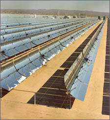
Source: US DOE (EERE)
The thermal absorber, a tube located at along the focal line of the mirror, contains the working fluid which is heated by the solar radiation to a high temperature and used to drive a heat engine.
An alternative concentrator arrangement is the Power Tower which uses a large array of parabolic mirrors focused on a solar furnace mounted on the top of a tower. Because of the long focal length, the mirrors are almost flat.

As with the trough concentrators, the solar furnace is used to raise steam to drive a turbine generator.

Source: U.S. NASA
Available Energy - Practical Systems
The table below shows the solar energy available at two extremes of latitude and provides an indication of the upper and lower limits of the solar energy falling on the Earth. The insolation (kWh/m2/day) is the monthly averaged incident energy falling on a horizontal surface at the given location. Also called the "Equivalent Sun Hours" or "Hours of Full Sun" (SeeDefinition)
Solar Energy Available at Different Latitudes | |||||
|---|---|---|---|---|---|
Location | Latitude Degrees | Altitude | Tracking | Insolation kWh/m2/Day | |
June | December | ||||
Anchorage, Alaska | 61.17°N | 35 | None | 4.5 | 0.6 |
2 Axis | 6.8 | 0.7 | |||
Quito, Equador | 0.47°S | 2851 | None | 4.38 | 4.81 |
2 Axis | 6.09 | 6.62 | |||
Source NREL
Because of cloud cover and pollution, the quoted hours of "full Sun" are substantially less than the actual hours of daylight. In sunnier climes, an average of 33% of solar irradiation comes from diffuse light but for the majority of locations this is typically more than 50%. The equivalent hours of full Sun takes into account the affect of overcast or partially cloudy skies.
System Dimensioning - Energy Capture
Much care is needed in specifying solar array sizes to meet system power requirements. Using yearly average insolation figures for the chosen location may be acceptable if all that is required is a grid connected system with an average annual generating capacity, but this is almost never the case and it certainly does not apply to stand alone systems.
Averages can be very misleading, even within the month.
The following table gives the monthly average, and yearly average, insolation at two locations in the UK.
Daily Insolation Levels (kWh/m2/day) at Locations in the UK | |||||||||||||||
|---|---|---|---|---|---|---|---|---|---|---|---|---|---|---|---|
Location | Latitude | Longitude | Jan | Feb | Mar | Apr | May | June | July | Aug | Sept | Oct | Nov | Dec | Average |
Edinburgh | 55' 55" N | 3" 10" W | 0.44 | 0.94 | 1.86 | 3.18 | 4.33 | 4.34 | 4.13 | 3.41 | 2.43 | 1.2 | 0.59 | 0.32 | 2.26 |
London | 51' 32" N | 0' 5" W | 0.67 | 1.26 | 2.22 | 3.48 | 4.54 | 4.51 | 4.74 | 4.01 | 2.86 | 1.65 | 0.89 | 0.52 | 2.61 |
Monthly Averaged Insolation Incident On A Horizontal Surface (kWh/m2/day)
Source NASA
If the system capacity were to be based on the yearly average, for most practical installations there would be a surplus of energy in the summer and a shortfall in winter. A stand alone system would have to be dimensioned to be able to provide the peak load during the winter months, otherwise an auxiliary source of power must be provided. The system would then be over-specified for the summer months and some form of reducing the capacity or dumping the excess energy must be found. A hybrid system combining wind and solar power could be the answer.
Energy Storage
Because no power is provided during the hours of darkness, the stand alone systems must generate and store sufficient energy during the day to satisfy the peak daily load. The storage should also be sufficient to cover several days when no sunlight is available. Batteries are normally used as a buffer to provide the necessary storage to guarantee short term continuity of supply by storing surplus energy during the day for use during the night and during periods of overcast skies. Unfortunately it is not practical to store the summer's surplus energy for use during the winter.
Solar Power Generation (Thermal)
Electricity generation in a solar thermal plant occurs in two stages. First the heat energy from the Sun is captured and used to heat a working fluid which is then used in a second energy transformation stage to generate the electricity. Note that the thermal energy comes from the Sun's radiation and not from the air whose temperature will usually be much lower than the temperature of the working fluid. The actual operating temperature reached by the working fluid will depend on the rate at which the thermal energy is being extracted by the working fluid (the flow rate) and delivered to the electricity generating system.
A solar thermal power plant usually has a system of mirrors to concentrate the sunlight on to an absorber, the absorbed energy then being used to power a heat engine which in turn drives a rotary generator. In large scale systems, the heat engine is usually a turbine driven by steam or other vaporous working fluid. In small scale systems the heat engine may be a Stirling engine.
Electricity Generating Systems
Large Scale Thermal Plants
The system below is designed to capture the thermal energy radiated from the sun.
Thermal energy from the Sun is intercepted by a concentrator which focuses the energy on a heat absorber containing the working fluid, usually a synthetic oil, which is heated by the solar radiation to a high temperature typically 400° C. The system may use a binary cycle in which the heated oil is passed through a heat exchanger to raise steam which is used to drive a conventional turbine and generator in a separate circuit.
To maintain the thermal efficiency of the turbine, the working fluid leaving the heat exchanger should not be allowed to cool down. Solar plants are therefore supplemented by gas-fired boilers which generate about a quarter of the overall power output and maintain the temperature overnight.
Several such installations in modules of 80 MW are now operating and solar conversion efficiencies of between 15% and 23% have been achieved. Each module requires about 50 hectares of land and needs very precise engineering and control. Power costs are two to three times that of conventional sources.
Small Scale Thermal Plants
Steam turbines are only practical for very large installations. Stirling Engines are often used in small systems to drive the electrical generator.
Domestic thermal generating plants typically use an array of water filled panels or a small array of parabolic trough concentrators to capture the Sun's thermal energy. Very small system such as those used in space applications may simply use a parabolic dish to capture the energy.

The working fluid is then used as the external heat source for powering the Stirling engine which in turn drives a rotary generator.
An off-grid stand alone solar electric system must have batteries supported by Balance-of-System (BOS) components including chargers, inverters and controllers to manage the energy flows in order to provide power on demand. This makes the system very expensive. Grid connected systems also need power conditioners and control systems if surplus energy is to be sold back to the utility company.
Efficiencies achieved with small scale systems range from 18% to 23%.
Domestic Water Heating Applications - A brief diversion
Many small domestic solar thermal systems are merely used for water heating and not for generating electricity.
- Practical Systems
- Water Temperature
- Temperature Limits
- Efficiency
- Economics
- Example
The working fluid is water, circulating through a rooftop mounted solar panel and fed directly into the domestic hot water system. As an alternative, the working fluid may be passed through a heat exchanger consisting of a coiled pipe in the hot water storage tank to heat the water indirectly.
The front surface of the solar panel is double glazed, allowing the Sun's radiation to pass through to heat up the water flowing through the panel while preventing heat loss from the warmer water due to convection and conduction in the opposite direction (from the panel to the colder atmosphere). The rear surface of the panel is also insulated to prevent heat loss in that direction.
The system works in cold weather because the water is heated by the Sun's radiation, not by the ambient air from which it is insulated.
An elegant, self regulating solution for maintaining the water temperature is provided by incorporating a small, subsidiary photovoltaic panel (see below) to generate the electrical energy needed to power the water circulation pumps instead of using mains electricity.
At sunrise, the pump remains switched off until the water reaches its operating temperature at which point the pump is switched on. As the Sun's radiation increases during the morning, the water temperature will rise, but at the same time the solar powered pump will run faster, increasing the water flow and thus transfering heat more quickly from the panel to the hot water storage tank. By suitably dimensioning the pump and the photovoltaic panel, the heat transfer rate from the panel can be matched to the heat absorption rate from the Sun thus maintaining a constant water temperature. As the received Sun's energy wanes in the afternoon the process is reversed, the pump runs more slowly reducing the rate at which heat is extracted from the panel thus maintaining its temperature. Being completely independent of the electricity grid, these systems have the added economic and environmental benefits that no electrical energy is drawn from the grid for running the pumps.
With water as the working fluid, the system is prone to freezing and boiling unless special precautions are taken. Low cost systems allow the water to freeze in very cold and dark environments by using flexible freeze-tolerant, silicone rubber pipework which is sufficient to accommodate the expansion of the water as it turns to ice. The volume of water used in solar thermal panels is very small, typically around 2 or 3 litres and is spread over a very large area to capture the maximum solar radiation. The high received radiation acting on a low water volume enables the water to heat up very quickly but for the same reason makes it susceptible to boiling. Unless there is a constant water flow to a storage tank with the heated water in the panel being replaced by cold water from the tank, the water could reach temperatures of 150 degrees C or more and for this reason the water pumps must be continually switched on. Even so, the possibility of boiling still remains, even with the pumps running, if the system is incorrectly dimensioned. The equilibrium temperature reached will depend on the balance between the solar energy captured by the panel and the thermal energy absorbed in the storage tank, the rate at which it is withdrawn from the tank and the system heat losses. Using a very small panel coupled to a very large tank with high hot water usage will result in a low water temperature in the tank. Conversely using a very large panel with a very small tank could result in boiling, particulaly if the hot water usage is very low. This need not be a disaster since the water content in the panel is very low and system could be designed to allow the steam to vent in case of boiling.
Energy conversion efficiencies achieved in these pure thermal applications may be three or four times the efficiency of photovoltaic applications though their applications are much more limited.
In higher latitudes the available solar energy captured by practical domestic installations may be sufficient to provide hot water for washing and showering but not enough to supply building space heating requirements during the colder months. Back-up heating systems will consequently be needed to cater for the base load to satisfy these requirements. Because the supply of solar energy is intermittent, the conventional heating system must fill in the gaps and there is little opportunity to downsize it. The householder will therefore, most likely have to pay the capital costs of a base load system capable of supplying the full heating load as well as the solar heating system even though the conventional heating system will not be working at full capacity most of the time.
Domestic solar thermal systems may not generate electricity directly but they do contribute to a reduction in the use of electrical energy and its associated costs.
Useful Energy Captured
The table above shows that in the UK, the average solar radiation received is about 2.5 kWh / M2 / day. A single solar panel with an area of 3 M2will therefore capture 2.5 x 3 x 365 = 2737 kWh of energy per year. With a system conversion efficiency of around 40% and less than optimal orientation of a typical rooftop mounted solar panel, the maximum usable energy received by a single panel system will be around 1000 kWh. This is roughly equivalent to the energy supplied by a 3 kW immersion heater used for one hour per day. As always however, averages can be misleading. In the summer, the solar panel could deliver an "average" of about 5 kWh of heating energy per day, but in the winter this could be as low as 0.4 kWh per day. The energy captured can of course always be increased by increasing the number of solar panels employed in the system.
Cost Savings
The cost saving will depend on whether the solar system is replacing 1000 kWh of heating energy supplied by a gas or an electric water heating system and the associated tarriff charged for the energy. With UK domestic gas currently costing less than £0.03 per kWh ($0. 045) and electricity costing about £0.10 per kWh ($0.15) the annual savings are likely to be somehwere between £30 and £100 ($50 to $150).
Since typical single panel installations cost around £2,500 or £3,000 ($4,000 to $5,000), unless the systems qualify for a government subsidy or there is a very large increase in energy costs, the payback time for the investment will be measured in decades rather than years. Saving the planet can be quite expensive.
Carbon Footprints
As with wind power, if the investment fails the conventional economic tests, the notion of carbon footprints is often used to jusify the expense, based on the potential for reducing the amount of greenhouse gases emitted by alternative methods of power generation.
See also Domestic Solar PV System Economics below.
Solar Power Generation (Voltaic)
Solar voltaic power generation is the direct conversion of solar energy into electricity.
Sunlight comes in many colours, combining low-energy (1.1 electronVolts (eV)) infrared photons with high-energy (3.5 eV) ultraviolet photons and all the rainbow of visible-light photons in between. Solar cells, also called photovoltaic or PV cells, are semiconductor devices designed to capture these photons and convert their energy directly into electrical energy.
How Solar Cells Work
When a photon with sufficient energy impinges upon a semiconductor it can transfer enough energy to a electron to free it from the bonds of the semiconductor's valence band so that it is free to move and thus carry an electric current. The junction in a semiconductor diode provides the necessary electric field to cause the current to flow in an external circuit.
A more detailed explanation of how solar cells work is given in the section on photovoltaic diodes.
The typical output voltage of a PV cell is between 0.5 and 0.6 Volts and the energy conversion efficiency ranges from less than 10% to over 20%. An array of cells can therefore generate about 200 Watts of electrical power per square metre when illuminated by solar radiation of 1000 Watts per square metre. The corresponding current density will be about 400 Amps/m2. Because of climatic conditions the intensity of the insolation rarely reaches 1000 W/m2.
Practical cells are also much smaller than one square meter with actual sizes of commercially available cells ranging from about one centimetre square to 15 centimetres square. The corresponding output Wattages for these cells range from 20 milliWatts to about 4 Watts.
- Standard Test Conditions (STC)
- Air Mass
- Rated Power
In order to compare solar cells on a like for like basis a set of Standard Test Conditions (STC) has been defined. The conditions are: normal irradiance of 1000w/m2 , cell temperature 25 °C and Air Mass =1.5
The receiving surface corresponding to AM 1.5 is defined as an inclined plane at 37° tilt (the average latitude in the USA) toward the equator, facing the sun. In this case, the surface normal points to the sun, at an elevation of 48.81°, its zenith angle, above the horizon.
Rated Power is defined as the maximum power (Wp or kWp) generated by the cell or module under the Standard Test Conditions.
Solar Cell Operating Characteristics
The graph below shows that with constant irradiance the output voltage of a cell or an array of cells falls as it is called upon to deliver more current.

Maximum power delivery occurs the voltage has dropped to about 80% of open circuit voltage voltage.
The Fill Factor (FF) is defined as the ratio between the power at the maximum power point and the product of the open circuit voltage and short circuit current. It is typically better than 75% for good quality solar cells.
 | The short circuit (SC) current is directly related to the number of photons absorbed by the semiconducting material and is thus proportional to light intensity. The conversion efficiency is therefore reasonably constant so that the power output is proportional to the irradiance down to fairly low levels, however the efficiency is reduced if the cell temperature is allowed to rise. The open circuit (OC) voltage varies only slightly with light intensity. |
|---|
As temperature increases, the band gap of the intrinsic semiconductor shrinks, and the open circuit voltage (Voc) decreases. At the same time, the lower band gap allows more incident energy to be absorbed because a greater percentage of the incident light has enough energy to raise charge carriers from the valence band to the conduction band. A larger photocurrent results. The increase in the current for a given temperature rise however is proportionately lower than the decrease in voltage. Hence the efficiency of the cell is reduced. |  |
|---|
Solar Cell Efficiency
The following graphs show the same information as those above but in a slightly different form showing how increased temperature reduces the efficiency.

In real outdoor conditions the rated peak power Wp is seldom achieved, since module temperature usually is more in the range of 40°C - 60°C. Efficiency can be improved by cooling the cells and some systems have been designed to make use of the heat absorbed by the cooling fluid in solar heating applications.
Solar Cell Types
Several types of solar cells have been developed with the aims of reducing costs and improving efficiencies.
- Crystalline Silicon Solar Cells
- Amorphous Silicon Solar Cells
- Thin Film Silicon Solar Cells
- Multi Layer (Tandem) Solar Cells
- Exotic Materials
- Electrochemical Solar Cells - Dye Sensitised Solar Cells (DSSC or Grätzel Cells)
Benefiting from the manufacturing experience of the semiconductor industry, crystalline silicon is the leading solar cell material, though still relatively expensive. Monocrystalline cells are cut from single crystals of high purity electronics grade silicon. These cells are about 25 percent efficient at best. Using the easier to manufacture polycrystalline silicon cut from from a block of crystals or less pure, so called "solar grade" silicon, efficiencies may be only about 15% or 16% due to the effect of grain boundaries or impurities but they cost a fraction of single crystal electronics grade cells.
Amorphous Silicon has been employed for many years in the manufacture the solar cells used for powering electronic calculators and watches and promises the possibility of low cost, higher power cells. Amorphous material appears like a solid but has no regular crystal lattice structure. Glass is an example of such materials. The presence of controlled quantities of certain "impurity" elements such as hydrogen and the random crystal lattice formation actually enhance the otherwise very low conversion efficiency. Typical cell efficiencies range from 5% to 10%.
Manufacturing yield is still a problem and the cells suffer from degradation when exposed to the sun.
Thin film cells are made by depositing the active photovoltaic material, such as amorphous silicon or other semiconductor onto a glass or other substrate together with the necessary current collecting contacts. The cell construction is much less costly than using semiconductor wafers and the manufacturing process is also simpler as well as being suitable for making cells with a much larger area and hence current carrying capability. Efficiencies of 11% to 14% have been achieved with this construction.
PV systems on flexible polymer substrates have also been made using Copper Indium Gallium Selenide (CIGS) active material with efficiencies of 10%.
Better conversion efficiencies are possible by using multiple layers of differing semiconductor materials, optimised for different wavelengths, in a single device. This can raise the theoretical efficiency limit, currently about 30% for a single junction device, to about 45% for a three junction cell.
Efficiencies of over 33% have already been achieved in practical devices.
Materials such as Gallium Arsenide, Copper Indium Diselenide, Cadmium Telluride and Indium Nitride have been employed to provide particular characteristics to optimise solar cells for specific applications.
Gallium Arsenide is used for military and aerospace applications in a variety of cells in combination with other elements because of it's suitability for capturing high energy photons (ultra violet radiation), high potential conversion efficiency and its ability to withstand high temperatures. It is however more difficult to manufacture and cells using Gallium Arsenide can be 100 times more expensive than commercial silicon based cells.
Copper Indium Diselenide and Cadmium Telluride are used in polycrystalline form in low cost thin film cells because of their ease of manufacture and reasonable yields. Efficiencies are however low ranging from 8% to 14%
Indium Nitride is suitable for capturing low energy photons (infra red radiation) making it suitable for full spectrum devices when used in tandem solar cells in combination with other materials such as Gallium Arsenide which capture the high energy photons.
Relatively new, these cells are low cost devices which use dye sensitised Titanium dioxide in combination with a liquid electrolyte to generate the current. Up to now they are only available in small sizes with efficiencies between 7% and 10%.
Solar PV Collectors
Solar cells are usually sold in modules built up from a number of cells arranged in series and / or parallel to provide convenient or commonly used voltages and power ratings.
Solar Arrays
Modules can be similarly interconnected to create larger arrays with the desired peak DC voltage and current.
Concentrators
As with thermal collectors, concentration of the incident energy on to a smaller surface is possible. For very small applications, optical mirrors and lenses are used.
Maximum Power Point Tracking (MPPT)
A power source will deliver its maximum power to a load when the load has the same impedance as the internal impedance of the power source. (Jacobi's Law). Unfortunately, batteries are far from the ideal load for a solar array and the mismatch results in major efficiency losses.
A typical PV array designed to charge 12 Volt batteries delivers its maximum power at an operating voltage around 17 Volts. Lead Acid batteries are normally charged up to 14 Volts though the voltage quickly drops to 12 Volts as they start to deliver current and lower still as the depth of discharge (DOD) increases.
In its simplest form, charging is carried out by connecting the PV array directly across the battery. The battery however is a power source itself and presents an opposing voltage to the PV array. This pulls the operating voltage of the array down to the voltage of the discharged battery and this is far from the optimum operating point of the array.
The diagram below shows the performance of a17 Volt, 4.4 Amp, 75 Watt PV array used to top up a 12 Volt battery. If the actual battery voltage is 12 Volts, the resulting current will only be about 2.5 Amps and the power delivered by the array will be just over 50 Watts rather than the specified 75 Watts: an efficiency loss of over 30%.
Maximum Power Point Tracking is designed to overcome this problem.

The power tracker module is a form of voltage regulator which is placed between the PV array and the battery. It presents an ideal load to the PV array allowing it to operate at its optimum voltage, in this case 17 Volts, delivering its full 75 Watts regardless of the battery voltage. A variable DC/DC converter in the module automatically adjusts the DC output from the module to match the battery voltage of 12 Volts.
As the voltage is stepped down in the DC/DC converter, the current will be stepped up in the same ratio. Thus the charging current will be 17/12 X 4.4 = 6.2 Amps and, assuming no losses in the module, the power delivered to the battery will be 12 X 6.23 = the full 75 Watts generated by the PV array.
In practice the converter losses could be as high as 10%. Nevertheless a substantial efficiency improvement is possible.
It is not enough however to match the voltage at the specified maximum power point (MPP) of the PV array to the varying battery voltage as the battery charges up. Due to changes in the intensity of the radiation falling on the array during the day as well as to changes in the ambient temperature, the operating characteristic of the PV array is constantly changing and with it the MPP of the PV also changes. Thus we have a moving reference point and a moving target. For optimum power transfer, the system needs to track the MPP as the solar intensity and ambient temperature changes in order to provide a dynamic reference point to the voltage regulator.
High performance MPPT modules may incorporate software algorithms to take account of the variations in insolation and temperature. A typical job for fuzzy logic or a neural network. Alternatively the optimisation can be accomplished in hardware by means of a perturbation signal incorporated in a feedback loop which drives the system operating point to the MPP.
A small dither voltage is superimposed on the PV voltage and its affect on the regulator output current feeding the battery is monitored. If the current drawn by the battery increases when the dither voltage increases, then the operating point has moved towards the MPP and therefore, the operating voltage must be increased in the same direction. On the other hand, if the current into the battery decreases, then the operating point has moved away from the MPP and the the operating voltage must be decreased to bring it back.
Large Scale Photovoltaic Plants
Several large scale grid connected PV power plants have been constructed throughout the world, mostly of 300 kW to 500 kW capacity but some as high as 10MW. Up to now deployment of large scale plants has been limited to experimental installations by the high cost of the solar panels. With typical efficiencies of 10% or less, a 500 kW plant will need over 5000 square metres of PV panels costing $1.0 per Watt as well as large scale inverters capable of handling the full system power output.
Small Scale Photovoltaic Plants and Domestic Applications
The diagram below shows the basic building blocks of a small stand-alone off-grid PV power generating system. A grid connected system would not need the battery and MPPT power tracking system. They do however need alternative capacity to come on stream to carry the load during the hours of darkness.

Photovoltaic System Dimensioning
- Array sizes for Photovoltaic System
- Example
- Grid-connected Systems
- Stand Alone Systems
- Costs
- Benefits
- Payback
- Selling surplus energy back to the utility company
- Balance of System (BOS) Components
The following example show the array sizes necessary to generate 10 kWh of usable energy with an average daily insolation of 2 kWh/m2/day. Note that the results are heavily dependent on the efficiency assumptions used.
Needless to say the array must not be shaded by objects such as trees or buildings.
Energy received per unit area = Insolation X Solar conversion efficiency.
Thus:
The area required for a given energy capture = Energy required ÷ ( Insolation at the desired location X Solar conversion efficiency)
Using an efficient (expensive) photovoltaic array with a conversion efficiency of 15% the area of the array will be:
10÷(2 X 0.15) = 33.3 m2
Insolation data is usually provided for the energy falling on a flat surface. By tilting the array to an angle corresponding to the latitude of the location, an extra 10% of energy can be captured reducing the area required to 30 m2. See the diagram showing Array Orientation
This advantage will be lost however if the array is to be mounted on a roof which is not optimally aligned towards the Sun.
If the array is free standing on the ground, and not constrained to be used on a roof, a solar tracking system can be used to enable more of the Sun's energy to be captured. A 30% improvement is possible reducing the required array area to about 21 m2
Note that the PV array output is DC electrical power.
To provide AC power there would be further electrical losses of 10% to 20% in the voltage regulator, inverter and control circuits.
Assuming 20 % electrical system losses, a fixed PV array with an area of around 36 m2, or a solar tracking PV array of 25 m2 would be required to provide 10 kWh of AC power per day.
Off-grid systems are subject to the same performance parameters as grid-connected systems however since they also use battery storage they suffer from an extra efficiency loss of up to 30% due to the back emf of the battery.
Unless an MPPT tracking system is used to reduce these losses the array would have to be 30% bigger to compensate. Thus to provide the same 10 kWh of AC power per day in a stand-alone system, the required PV array area would have to be 47 m2 for a fixed installation and 33 m2 for a solar tracking system.
Electricity consumption in many households in Europe and the USA is 2 or 3 times more than 10 kWh per day, particularly for those willing to invest in solar PV electricity generation. (See Energy Demand Table). This implies that very large PV arrays with areas up to 150 m2 or more, probably larger than the available South facing roof surface, would be needed to satisfy their energy demands.
All of the above is based on an average insolation of 2 kWh/m2/day, but in northern temperate zones the winter insolation is likely to be less than a quarter of the average for the location. See the table for Energy Availability and Energy Capture above. Thus the available energy will be only 2.5 kWh/day during the winter months or the systems would need to be four times bigger in order to supply the same 10 kWh/day of electrical energy in the winter.
Domestic Solar PV System Economics
Example
According to the UK Government Energy Saving Trust, the costs for installing a solar PV system vary greatly. An average domestic system is quite small generating around 2.2 kWp and costs around �12,000 ($18,000). Larger solar electricity systems can cost in the region of �4,500 ($7,000) to �8,000 ($12,000) per kWp, reducing slightly as the system size increases.
A 2.2 kWp system only delivers the full 2.2 kW of power under Standard Test Conditions of 1000 W/m2 insolation. It would generate 52.8 kWH (52.8 Units) of electricity per day if the Sun was directly overhead and shining constantly day and night. But the table above shows that the average insolation in the UK is only about 2.5 kWh/m2/day. This is equivalent to 2.5 hours of full Sun (see EHS above) per day, not 24 hours. Thus the actual electrical energy output from the PV system in the UK will be about 5.5 kWh per day or 2,000 kWh per year.
Buying 2,000 kWh of electrical energy from the local utility company would cost £200 ($300) with the curent costs of electricity at £0.10 ($0.15) per unit. Ignoring maintenance costs, this gives a payback period of sixty years.
Fortunately, many governments provide generous grants to subsidise the installation and/or operation of solar power systems thus reducing the capital outlay and decreasing the investment payback time.
The average UK household consumes about 5,000 kWh of electrical energy per year or around 14 units per day. The likelihood of a domestic installation as described above having regular surpluses is quite remote.
Furthermore, feeding electrical energy back into the grid involves the obligatory installation of additional, costly metering and safety systems as well as synchronisation electronics so that this option is only economically justifiable for installations with relatively large surplusses.
Beware when the solar panel salesman comes knocking!
See also Domestic Solar Heating and a comparison of Electricity Generating Costs for different fuels.
The associated BOS components needed to complete the system are described in the section on Small Scale Systems.
- Other PV System Considerations
Converting the direct current output of the PV array to alternating current is both costly and inefficient. Some of this cost and waste can be avoided by using household appliances designed to run on DC power where they are available.
Similarly it is not sensible to run heaters from PV systems.
- 0
Harsh Arora answered this
Electrical Machines - Electric Drives
(Fundamentals)
Principles

- Motor Action
- Generator Action
- Alternative Motor Action (Interactive Fields)
- Reluctance Torque
- Salient Poles
- Torque from Rotating Fields
- Slip
- Torque Angle
- Electrical Machines
The majority of electrical machines (motors and generators) sold today are still based on the Lorentz force and their principle of operation can be demonstrated by the example below in which a single turn coil carrying electrical current rotates in a magnetic field between the two poles of a magnet. - Action and Reaction
- The EMF Equation
- The Power Equation
- Operating Equilibrium Under Load
- Magnetic Fields
The motor's magnetic field is provided by the stator and in the above example the stator is a permanent magnet however in the majority of electrical machines the magnetic field is provided electromagnetically by coils wound around the stator poles. The stator windings are also called the field windings and the motor is said to be "field energised".
The rotor is normally wound on an iron core to improve the efficiency of the machine's magnetic circuit.- Magnetic Circuits
In the case of electrical machines, the magnetic circuit is the path of the magnetic flux through the stator body, across the air gap, through the rotor and back through the air gap into the stator. The length l of this path is known as the mean magnetic path length MMPL
Magnetic circuits are designed to produce the maximum flux possible and to concentrate it in the air gap between the rotor and the stator through which the coils move. The flux Φ is measured in Webers
The flux density B is measured in Teslas and is defined as the magnetic flux Φ per unit area A. Thus B = Φ/A where A is the area through which the flux passes.
- MagnetoMotive Force (MMF)
The magnetic flux arising in a magnetic circuit is proportional to the magnetomotive force (MMF) creating it. For an electromagnet, the MMF is the effective current in the magnetising coil measured in Ampere turns NI and, as above, this is the actual current I times the number of turns N in the coil.
Thus MMF = NI = Φ X R where R is the reluctance of the magnetic circuit. The reluctance is the inherent resistance of the material in the magnetic circuit to the setting up of the magnetic flux through it. (For iron the reluctance is very low. For air it is very high)
This equation for the flux in magnetic circuits is analogous to Ohm's law for the current in electric circuits in which:
EMF = I X R where R is the resistance of the electric circuit.
Because the reluctance of the air gap between the stator and the rotor is very high, the air gap should be as small as possible to minimise the Ampere turns needed to create the desired flux density. - Magnetic Force (H) also called the Magnetic Field Strength
- Flux Density (B) and Magnetic Permeability (µ)
- Saturation
- Magnetic Poles
Electric machines can have multiple pole pairs. Multiple pole machines usually provide more efficient magnetic circuits and smoother torque characteristics.
From the equations above it can be seen that the torque generated by the electric motor or the EMF created by the generator are directly proportional to the magnetic flux density B in the region surrounding the moving electrical conductors and for efficient machines, B should be as high as possible.The magnetic field strength H is the MMF per unit length in a magnetic circuit. Thus:
H=NI
l
The magnetomotive force is the cause of the magnetic field, the magnetic force is the effect.
For uniform fields, the flux density associated with the magnetic force is proportional to the field strength and is given by:
B=µ0µrH
where
µ0 is the known as the magnetic constant or the permeability of free space.
µr is the relative permeability of the magnetic material.
Unfortunately, the relationship becomes non-linear as the flux density increases and the magnetic material becomes saturated. Then the flux produced by increases in the the magnetic field decreases and levels off and the relaitive permeability µr tends towards 0.

From the above it can be seen that increasing the MMF (Ampere turns) in a magnetic circuit increases the flux through the circuit but there is a limit to the flux density which can be created in magnetic materials such as iron when the material is said to be saturated. Above this point more and more MMF is needed to create less and less flux. In other words the reluctance increases sharply when the material saturates.
For maximum efficiency, electric machines are usually designed to work just below the onset of saturation.
- Magnetic Circuits
- Commutation
- Evolution
Michael Faraday showed that passing a current through a conductor freely suspended in a fixed magnetic field creates a force which causes the conductor to move through the field.
Conversely, if the conductor rather than the magnet is constrained then the magnet creating the field will move relative to the conductor.
More generally, the force created by the current, now known as the Lorentz force, acts between the current conductor and the magnetic field, or the magnet creating the field.
The magnitude of the force acting on the conductor is given by:
F = BLI
Where F is the force on the conductor, L is the length of the conductor and I is the current flowing through the conductor
Faraday also showed that the converse is true - moving a conductor through a magnetic field, or moving the magnetic field relative to the conductor, causes a current to flow in the conductor.
The magnitude of the EMF generated in this way is given by:
E = BLv
Where E is the generator EMF (or back EMF in a motor) and v is the velocity of the conductor through the field
Another form of motive power, which does not depend on the Lorentz force and the flow of an electrical current, can in principle be derived from the purely attractive (or repulsive) magnetic force which is exerted on a magnet or on magnetically susceptible materials such as iron when they are placed in the field of another magnet. The movement of a compass needle in the presence of a magnet is an example. In practice however at least one magnet creating the field must be an electromagnet in order to obtain the necessary control of the magnetic field to achieve sustained motion as well as practical levels of torque.
Brushless DC motors and reluctance motors depend on this phenomenon known as "reluctance torque" since no electric currents flow in the rotor. Rotary motion is obtained by sequential pulsing of the stator poles to create a rotating magnetic field which drags along the moving magnet with it.
In AC induction motors the rotating field is obtained by a different method and the basic motor action depends on the Lorentz force, however synchronous AC motors have magnetic rotor elements which are pulled around in synchronism with the rotating field just as in a brushless DC motor.
Torque is created due to the reaction between magnetic fields. Consider a small bar magnet in the field of another larger magnet such as the gap between the poles of a horse shoe magnet or one of the pole pairs of an electric motor. (See reluctance motor diagram). When the bar magnet is aligned with the poles of the large magnet its field will be in line with the external field. This is an equilibrium position and the bar will not experience any force to move it. However if the bar is misaligned with the poles, either rotated or displaced, it will experience a force pulling it back into line with the external field. In the case of a lateral displacement, the force diminishes as the distance increases, but in the case of a rotation, the force will increase reaching a maximum when the bar is at right angles to the external field. In other words the torque on the magnet is at a maximum when the fields are orthogonal and zero when the field are aligned.
Motors which depend on reluctance torque normally have "salient poles" - poles which stick out. This is to concentrate the flux into discrete angular sectors to maximise and focus the alignment force between the fields.
In motors which depend on rotating fields, such as induction motors, brushless DC and reluctance motors, the instantaneous torque on the rotor depends on its angular position with respect to the angular position of the flux wave. Though the flux wave tries to pull the rotor poles in line with the flux, there will always be inertia and losses holding the rotor back.
The friction, windage and other losses cause the rotor of an induction motor to turn at a slower speed than the rotating field resulting in an angular displacement between the rotating flux wave and the rotating field associated with the rotor poles. The difference between the speed of the flux wave and the speed of the rotor is called the "slip" and the motor torque is proportional to the slip.
Even in synchronous motors in which the rotor turns at the same speed as the flux wave, because of the losses noted above the rotor poles will never reach complete alignment with the peaks in the flux wave, and there will still be a displacement between the rotating flux wave and the rotating field. Otherwise there would be no torque. This displacement is called the "torque angle". The motor torque is zero when the torque angle is zero and is at its maximum when the torque angle is 90 degrees. If the torque angle exceeds 90 degrees the rotor will pull out of synchronism and stop.

For multiple turn coils, the effective current is NI (Ampere Turns) where N is the number of turns in the coil.
If the coil is supplied with a current the machine acts as a motor. If the coil is rotated mechanically, current is induced in the coil and the machine thus acts as a generator.
In rotating machines the rotating element is called the rotor or armature and the fixed element is called the stator.
In practice, both the motor and the generator effects take place at the same time.
Passing the current through a conductor in the magnetic field causes the conductor to move through the field but once the conductor starts moving it becomes a generator creating a current through the conductor in the opposite direction to the applied current. Thus the motion of the conductor creates a "back EMF " which opposes the applied EMF.
Conversely moving the conductor through the field causes a current to flow through the conductor which in turn creates a force on the conductor opposing the applied force.
The actual current which flows in the conductor is given by:
I = (V - E)
R
Where V is the applied voltage, E is the back EMF and R is the resistance of the conductor (the armature of the motor)..
From the above, the back EMF in an electric motor is equal to the applied voltage less the volt drop across the armature.
E = V - RI
This is known as the "Motor EMF Equation".
The volt drop across the amature RI is sometimes called the Net Voltage
Multiplying the voltage by the armature current to get the power gives the following relationship:
P = EI = VI - I2R
It shows that the mechanical power delivered by the motor is equal to the back EMF times the armature current OR the electrical power applied to the motor less the I2R losses in the windings. (Disregarding frictional losses).
This is known as the "Motor Power Equation".
The "Action and Reaction" effects outlined above provide an important automatic self regulating feedback mechanism in both DC and AC motors for adapting to changes to the applied load. As the load on the motor is increased it tends to slow down, reducing the back EMF. This in turn allows more current to flow generating more torque to accommodate the increased load until a point of balance or equilibrium is reached. Thus the motor will set itself to an appropriate speed for the torque demanded. See alsoPower Handling below.
The connection to the moving coil in the basic machine shown above is made via carbon brushes bearing on a pair of slip rings, one connected to each end of the coil.
If the machine is used as a generator, the direction of the current generated will reverse every half cycle as the arm of the coil passes the opposite poles in succession. If a unidirectional current is required, the slip rings are split and interconnected such that, each half cycle, the current is taken from alternate arms of the coil. This simple switching mechanism is called a commutator.
Similarly when the machine is used as a DC motor, the commutator switches the DC supply voltage to alternate arms of the coil each half cycle in order to achieve unidirectional rotation.
Thus in all wound rotor DC machines, both motors and generators, the current in the rotor windings is AC and it is the commutator which enables the corresponding DC input or output. There are however some notable exceptions. The world's first motors and generators invented by Faraday were unipolar or homopolar machines in which unidirectional current flowed in the conductors. Faraday's motor was a laboratory curiosity with no practical applications but his so called "Faraday Disk" dynamo was able to generate useful current.
For over 100 years, mechanical commutation was the only practical way of switching the direction of the current flow however since the 1970s the availability of high power semiconductors has made electronic commutation possible.
In AC machines the complexities of commutation can be avoided since current can be induced in the rotor windings by transformer action with the stator windings, obviating the need for direct connections between the supply line and the rotating windings. See Induction Motors.
Because the commutator is essentially a mechanical switch, rapidly making and breaking a high current circuit, the switch is prone to sparking and the generation of Radio Frequency Interference (RFI) which can disrupt the working of other electronic circuits in the vicinity.
In very large motors the propensity for sparking can be reduced by the addition of "interpoles" or "commutating poles", narrow auxiliary windings midway between the main stator poles. These are connected in series with the rotor windings and produce an MMF equal and opposite to the rotor MMF so that the effective flux between the main poles is zero. Commutation is designed to occur the instant when the current passes through zero between the negative and positive half cycles and this takes place when the rotor is midway between the main poles. By neutralising the flux in this region the possibility of sparking is reduced.
The earliest electrical machines depended on permanent magnets to provide the magnetic field, however the best magnetic materials available at the time were only capable of providing very weak fields limiting potential machine applications to laboratory demonstrations. It was eventually realised that much stronger magnetic fields could be generated by using electromagnets powered by the applied or generated line voltage. This allowed the construction of much more powerful machines enabling the development of practical applications. Advances in magnetic materials have now created much more powerful permanent magnets enabling their use in practical machines, simplifying machine construction by eliminating one set of windings. At the same time many features such as encoders, tachogenerators, thermal cut outs, brakes and fans are being built into the machines See also Controllers
Motor Characteristics
Some general points
- Torque
- Speed
- DC Motors
- AC Motors
In DC motors the rotational speed is proportional to the applied voltage and the normal method of speed control is by varying the input voltage.
N = K2 V
B
The speed is however also inversely proportional to the flux in the air gap. This means that the speed increases as the flux provided by the field coils decreases. Theoretically the speed could go to infinity if the current in the field coil is removed, though the motor would most likely be destroyed before this happens. In practice a limited increase in speed can be obtained by reducing the field current in a controlled way. But note from the Torque equation above that reducing the field current also reduces the torque. This method of speed control is called "Field Weakening"
In AC motors the speed is proportional to the frequency of the applied voltage and inversely proportional to the number of magnetic poles.
N = K3 f
P
- Torque - Speed Characteristic
- Starting
- Power Handling
- Maximum Power
- Corner Power
- Cooling
- Gearing
- Size
- Efficiency
- Cogging
- Losses
Losses reduce the efficiency of the machine and usually result in unwanted heat.- Copper losses
These are the I2R heat losses resulting from the current flowing in the windings. The copper losses are variable, depending on the current and hence the load on the machine. The iron and other losses tend to be relatively constant.- Stator winding resistance
- Rotor winding resistance
- Iron Losses
These are losses which occur in the magnetic circuit.- Saturation
- Hysteresis loss
This is the energy needed to magnetise and demagnetise the iron in the magnetic circuit each machine cycle. Since the losses per cycle are fixed, they will increase in line with the frequency. See more information about hysteresis. Special low hysteresis steels have been developed to reduce these losses. - Eddy current loss
These losses are due to the unwanted, circulating currents which are induced in the iron of the machine's magnetic circuit by the machine windings. They are minimised by using laminated iron in the magnetic circuits instead of solid iron. The insulating oxide layer on the laminations inhibits eddy current flow between laminations.
This is the wasteful use of energy associated with using materials at flux densities above the saturation point.
- Flux Leakage
- Windage / Friction
- Power Factor
In practical magnetic circuits it is not always possible to concentrate all of the magnetic flux where it is needed for optimum magnetic coupling and the maximum energy interchange between the rotor and the stator. Consequently some of the applied energy is lost.
These are the mechanical losses resulting from the drag on the movement of the rotor.
An induction motor appears to the power line as a large inductor and consequently the line current lags behind the applied voltage. The effective power of the motor will then be VAcosΦ where V is the applied voltage, A is the current which flows and Φ is the phase angle by which the current lags the voltage.
CosΦ is known as the power factor. When Φ = 0 the current is in phase with the voltage, cosΦ = 1 and there is no power loss. When Φ = 1 the current lags the voltage by 90°, cosΦ = 0 and there will be no effective power delivered to the load. The factor (1 - cosΦ) represents the extra power which the machine must consume from the source in order to deliver its nominal power.
- Copper losses
Generally speaking the torque produced by a motor is proportional to the current it consumes and also proportional to the flux in the air gap.
T = K1I B
DC motors produce their maximum torque at zero speed or when they are stalled (when they consume maximum current) and the torque falls off linearly as the speed increases, reaching zero when the reverse voltage generated by the rotating coils in the magnetic field (the back EMF) is equal to the applied voltage.
With AC motors the starting torque at zero speed may be about 70% to 90% of its maximum, rising to a peak as the speed increases then falling sharply to zero as the motor approaches synchronous speed. See note about synchronous motors .
(The torque - speed characteristics of electric motors are in contrast to an internal combustion engines whose torque is very low at low speeds, typically stalling below 800 rpm, but increasing with speed up to a peak at about 80% of its maximum speed falling off only slightly as it reaches maximum speed.)
Some motor designs are not self starting in their basic configuration but they normally incorporate design adaptations to enable self starting so that the user may be unaware of the problem.
The motor output power is directly proportional to its speed.
The output power P in Watts is given by:
P = ωT
Where ω is the speed in radians per second and T is the torque in Newton metres
OR
P = 2π NT = NT
60 9.55
Where N is the speed in revolutions per minute (RPM)
NOTE: This relationship shows that for a given power, the speed reduces as the load or torque increases and vice versa. This is in some ways equivalent to what occurs in a mechanical gear box and is in line with the Operating Equilibrium mentioned above.
The maximum power which a motor can handle is determined by its maximum permissible temperature. Power handling capacity can be increased by utilising materials capable of withstanding higher temperatures, particularly for the insulation on the windings, or by providing forced cooling which lowers the motor temperature for a given current consumption.
Corner power is an alternative way of specifying motor performance which some people find useful for comparing machines.
It is simply the product of the maximum torque the motor can deliver and the maximum speed it can attain. Since the maximum torque rarely, if ever, occurs at the same time as the maximum speed, the actual delivered machine power will always be less than the corner power.
In DC motors the commutation limit is set by the ability of the commutator segments and brushes to handle high voltages (speed limit) and high currents (torque limit).
Note also that at high voltages and currents forced cooling may be required.
The power handling capacity of an electrical machine is limited by the maximum allowable temperature of its windings.
Higher power motors require higher magnetic fields and the current necessary to provide the higher flux density increases linearly with the motor size. The cross sectional area of the copper cable necessary to carry the current however increases as the square of the cuurent.
Power handling can be increased by using insulation which can withstand higher temperatures or by providing forced cooling to remove the heat from the windings. Forced cooling is not normally required for fractional horsepower machines but larger integral horsepower motors usually incorporate a built in cooling fan to force air through the machine. Forced air cooling can be effective in machines up to 50 megawatts but larger machines with multi megawatt power ratings, as used in the electricity generating industry, must resort to liquid cooling with the coolant being circulated through hollow conductors. The working fluid may be water but for the largest machines hydrogen is used because of its low weight and high thermal capacity.
For a given torque, the motor power is proportional to the speed. Low speed motors will thus deliver very low power. Applications requiring high torque at low speeds will require very high currents and impractically large motors. Such applications are better served by higher speed motors with gearing mechanisms to reduce the speed and increase the torque.
The size of a motor is determined by the torque it has to deliver. For similar motors with similar cooling systems the motor torque is proportional to the volume of the rotor and hence the overall motor volume.
As noted above, for a given torque, the motor power is proportional to the speed whereas the electrical and windage losses tend to be roughly constant, rising relatively slowly. Thus the motor efficiency increases with speed.
Efficiency is also dependent on the size of the motor since resistive losses tend to be proportionately much higher in smaller devices than in larger machines which can be designed with more efficient magnetic circuits.
Cogging is the jerky, non uniform angular velocity of a machine rotor particularly apparent at low speeds in motors with a small number of poles. It occurs because the rotor tends to speed up as it approaches the stator poles and to slow down as it leaves the poles. It is also noticeable when pulsed DC is used if the frequency of the supply waveform is too low. The problem can be reduced by using skewed rotor windings as well as increasing the number of poles in the motor.
Generators
As noted above, because of the reaction of the system to an applied force, all rotating machines are simultaneously acting as both motors and generators. The same electromagnetic forces are in play in both cases and the same equations represent the behaviour of the machines in both applications.
Note
- The voltage generated in any DC generator is inherently alternating and only becomes DC after it has been rectified by the commutator.
- Although rotating machines generate alternating current, it is not necessarily purely sinusoidal. The wave shape depends on the size of the poles and spacing between them, the distribution of the windings and the level of flux in the air gap. The output waveform at the generator terminals is likely to be somewhat distorted in all but the most complex of machines.
- 0